
Heat exchangers are an important part of the PE exam and are potentially featured in both the HVAC/Refrigeration and thermal/fluids systems exams. Three common exchanger types are outlined below as well as variations on each type.
These represent the majority of exchangers in industry and the three most likely to be featured on the exam in some way. Of these, the shell and tube type is overwhelmingly the most common style and the one you should start your studies with. But first let’s go over the main theory behind heat exchangers and how to use these concepts applicable to the exam.
The overall heat transfer equation for heat exchangers is defined as:
Where,
Q = the heat transfer (Btu/hr)
U = the overall heat transfer coefficient (Btu/hr-F)
Tm = Log mean temperature difference (F)
A = Heat transfer area (ft2)
PE exam strategy: Alternatively, if you know the working fluid and are given a mass flow rate and the inlet and exit temperatures of the fluid, you can calculate Q with the following:
Q=mc_p ∆TThis would be the “1st law” approach and is in my opinion a much simpler method that saves time and leaves less room for error than some of the relatively more complex equations shown in this section. The methods shown in this section pertain to exam problems involving heat transfer coefficients. Knowing which method to use depends entirely on what parameters you are given. Given mass flow and a specific fluid? Use mcp. Given a heat transfer surface area, or overall heat transfer coefficient? Use the overall heat transfer equation shown above.
Let’s look at each of these in detail.
This one should be obvious. This is the rate at which the heat exchanger transfers heat between the two mediums. In the case of shell and tube and plate and frame exchangers these two mediums are fluids. With air exchangers the two mediums are usually one fluid and one gas (air). Typical units are btu/hour but can be any unit of heat over time (calorie/minute, joule/hr, etc.)
This is one of the more complicated portions of the equation and requires some calculations in and of itself to determine (unless it’s given in a problem statement). In reality, the overall heat transfer coefficient for a heat exchanger is difficult to determine exactly and is usually given as an approximation or “rule of thumb” In essence, the overall heat transfer coefficient is the total of the rates of conduction and convection between both fluid streams. Conceptually, this equation looks like:
or
Where:
h = convective heat transfer coefficient (Btu/hr-ft2-F)
x = thickness of the wall (ft)
k = thermal conductivity (Btu/hr-ft-F)
A = heat transfer surface area (ft2)
The convection portion of the overall heat transfer coefficient has a geometry component. This is the “x” in the equation above. The final form of the overall heat transfer coefficient equation depends on the geometry of the heat exchanger itself. The three major shapes are a plane wall, a cylindrical wall, and a spherical wall. For the simple case of a segmented pipe heat exchanger (Fig 1), the geometry of the interface between the two heat mediums is a plate:
In this case your overall heat transfer coefficient equation would be the addition of the conduction through the plate and the convection occurring in each fluid:
The geometry of the heat transfer surface for a simple shell and tube heat exchanger is shown in figure 2:
In the case of a simple shell and tube heat exchanger with a single tube like the one above, your overall heat exchanger coefficient calculation becomes:
Likewise for a spherical exchanger your heat transfer coefficient looks like:
PE exam strategy: The examples shown here are for simple heat exchangers mostly to outline the concept of what an overall heat exchange coefficient is. Actual heat exchanger transfer coefficients can be much more complicated to determine. Many are determined experimentally. Always remember that the PE exam is a test of core competencies, not necessarily complexity. As such you probably shouldn’t expect anything more complex than what is shown here with the obvious caveat that I don’t have any affiliation with NCEES, and I don’t know (and can’t tell you) what will be on the exam.
The log mean temperature difference (LMTD) is just what it sounds like. It’s a logarithmic average of the temperature difference between the two working fluids in the exchanger. LMTD is defined as:
The LMTD is used instead of the actual temperature difference between the two incoming fluids because the temperature streams don’t remain at constant temperatures as the two fluids move through the heat exchanger, therefore an average is used to determine the overall heat transfer.
You’ll hear shell and tube exchangers described most commonly as single-pass, double-pass, counter flow, parallel flow, straight tubed and U tubed. These are all just variations on their geometric configuration. Below are some schematics of various types of shell and tube heat exchangers.
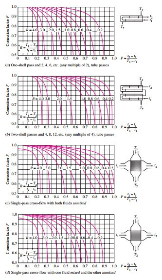
The only effective difference these configurations make as far as practical analysis lies in the introduction of a correction factor. The basic derivations for overall heat transfer are based on simple single pipe straight through or split pipe shell and tube exchangers as shown in Figure 1 and Figure 2. The log mean temperature difference for each of these configurations will change, as such a correction factor is needed to correct for the change to heat transfer these different configurations make. These LMTD correction factors are read off of charts. Many of these will be in your MERM. Alternatively they are easy to find on the internet. Here are some examples courtesy of Cengel, Y. A., Turner, R. H., Cimbala, J. M. (2012) Fundamentals of Thermal-fluid Sciences, 4th edition, London: McGraw Hill Higher Education:

For any questions or corrections on this material drop us a line at info@passthepeexam.com